Detailed STRANDS system setup
This readme will guide you through the setup and use of a system which uses the STRANDS packages. It is assumed that you have a system that is running Ubuntu 14.04. If you just want to get something running quickly, see the quick setup page.
ROS and package setup
Installing ROS
The first step is to follow the instructions found at
http://wiki.ros.org/indigo/Installation/Ubuntu. The full install of ROS
with the package ros-indigo-desktop-full should contain all the
base ROS packages that are required.
Installing STRANDS packages
To install the strands packages, you should follow the instructions at https://github.com/strands-project-releases/strands-releases/wiki.
Custom system setup
Database
While the system is running, it will store data in a mongodb database so that various components can access it. Depending on what tasks you are running, the database can grow quite large (on the order hundreds of gigabytes), so you should create the database on a drive with a lot of space.
The database will be automatically created by the database node, but requires the creation of a directory before it is launched. Running the following will initialise the database. The database is launched in the same way when the full system is running - it should be run before any other part of the system runs, as many of them require it to be up.
DATA_DIR=/my/data/directory
mkdir -p $DATA_DIR/my_database_dir
roslaunch mongodb_store mongodb_store.launch db_path:=$DATA_DIR/my_database_dir
You can see more information about the database system at https://github.com/strands-project/mongodb_store/tree/hydro-devel/mongodb_store
Using a simulation
You can use a simulated environment in order to test the system, either with existing simulated environments, or you can set things up to simulate the environment you wish to operate in. Later on in this document, there are instructions on how to set up a metric map and topological map. These can both be applied in a simulated environment as well.
Existing simulations
Simulations are based on the strands_morse package. If you look in
there, you’ll find several real environments which have already been set
up. We’ll look at the strands_morse/bham directory here.
The maps directory contains maps, as you might expect. There are
yaml and pgm map pairs for the ROS grid maps. The tplg file is a yaml
export of the topological map for that area.
The urdf directory contains urdf files for the environment, which
make use of dae files in the meshes directory.
The launch directory contains some launch files which can be used to
launch everything with just one command.
The top level python files are used to construct various environments, setting up the robot position, model and so on.
Before starting the simulation, you’ll need to add the topological map to your database using
rosrun topological_utils load_yaml_map.py `rospack find strands_morse`/bham/maps/cs_lg_sim.tplg
Once this is done, run
roslaunch strands_morse bham_cs_morse.launch
This will bring up the blender window with the environment loaded and populated with objects and a robot.
roslaunch strands_morse bham_cs_nav2d.launch
Will bring up all navigation and related nodes.
Finally, use rviz to visualise the map and topological map:
roslaunch strands_morse bham_default_rviz.launch
To allow the robot to move, you’ll have to move it backwards first - you can do this by pressing the down arrow on your keyboard when focusing the blender window. Once you’ve done that, you can click the green arrows to make the robot navigate there, or you can specify a navigation location using the 2d nav goal tool in rviz.
Custom simulations
To set up a custom simulation, you’ll first need to generate a 3D environment to use. A simple environment is easy to construct. You’ll need to have GIMP, inkscape and blender installed to create it.
If you want to skip the details, you can find the files created by this
section
here.
You will still have to add the topological maps to your mongo database
with rosrun topological_utils load_yaml_map.py maps/basic_map.tpl.
PNG map
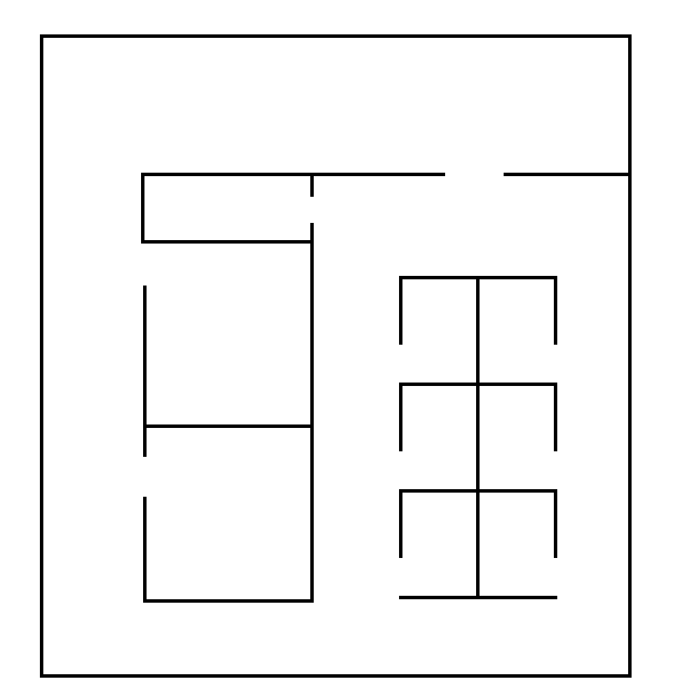
The first step is to use GIMP to create an image of the walls in the map that you want to use. The image below is made using the pencil tool and holding ctrl+shift to make straight lines. It has a scale of 35px/cm. We’ll use this later to scale the environment to our robot.
You can make something like this map using blueprints for the area you are working in and the process below should be similar.
SVG map
Once you have an image which contains only black and white pixels, open
inkscape and import the image, with the embed option.
Make sure the image is selected, and then open the trace bitmap
dialogue with alt+shift+b. Select the single scan colour quantisation
option, with 2 colours, and check the box to invert the image. Click the
update button on the right hand side and you should see the result of
the tracing. This tracing will convert the image into a vector graphic
which can be used in blender. You can fiddle with the options until you
get a result that looks good. Once you’re satisfied, press the OK
button. Then, save the image as an svg file.
Blender model
Open blender, and delete the cube that is in the space with the delete
key. Then, with file>import import the svg that you just created.
You should see it in the space as some black lines. You can select it in
the top right hand side, where it will exist as a curve. The image we
started with had a scale of 35px/cm, which will be very small for our
robot, which is around 80cm across (assuming that we’re using the Scitos
G5). On the right hand toolbar, you should see a set of icons - a
camera, some photos, a chain link, a cube, and so on. Select the cube
icon. This Will bring up a set of options which include scaling. In the
image, some openings which could represent doors are approximately 50
pixels wide. We’ll make these openings 1.5 metres wide, to make them
easy to get through. This means that each pixel has to be 0.03 (1.5/50)
metres. At 35px/cm, each pixel in the image was 0.000286 metres. So, in
order to get the size we want, we should scale each pixel by
approximately 105 (0.03/0.000286). We’ll apply this scaling to both the
x and y axes.
Once that scaling is done, we also need to make some proper 3D walls with height. Select the curve icon on the right hand side, and you should see under the geometry section the option to extrude. Set this value to 1.5 and it should be OK. Since extruding goes in both vertical directions, shift the model up by 1.5 in the transform options in the cube section.
We also need a floor, so add a plane in using add>mesh>plane. Scale
it so that it covers approximately the area needed to cover all the
floor space in the map, and transform it so that it sits below the
imported map. You may wish to translate or rotate the map so that it
sits in the positive quadrant of the space - when it is imported it will
sit on the positive x axis but negative y axis.
There also needs to be a light source so you can see what is going on.
Instead of the weak lamp that currently exists in the space, you should
add a sun (add>lamp>sun), which provides much more light.
The final step is to convert the curve to a mesh so that it is correctly displayed. With the curve selected, press alt+c, which will bring up a conversion menu. Use “mesh from curve” option, and then save the blender file.
You can find example files created from this process here.
Creating the simulation files
Now that we have all these models, we need to create some files to run everything. We’ll put everything into a new package for convenience.
First, create a new ros package in your workspace.
roscd
cd src
catkin_create_pkg basic_example
cd basic_example
mkdir scripts
In the scripts directory, create a script simulator.sh that will be
used to run the simulation. Its basic contents should look something
like the following. It sets up various paths and then runs another file
which defines what the simulation environment actually looks like:
#!/bin/bash
environment_name="basic_example"
strands_morse=`rospack find strands_morse`
example=`rospack find basic_example`
path="$example"
common="$strands_morse/strands_sim"

PYTHONPATH="$path/src:$common/src:$PYTHONPATH"
MORSE_RESOURCE_PATH="$strands_morse:$common/data:$common/robots:$path:$MORSE_RESOURCE_PATH"
export MORSE_RESOURCE_PATH PYTHONPATH
added=`$strands_morse/morse_config.py $environment_name $path`
echo "Running morse on $path with PYTHONPATH=$PYTHONPATH and MORSE_RESOURCE_PATH=$MORSE_RESOURCE_PATH"
PATH=/opt/strands-morse-simulator/bin:$PATH

morse run basic_example `rospack find basic_example`/example_sim.py
Don’t forget to run chmod +x scripts/simulator.sh to make it
executable.
In the top level directory, create the simulation definition
(example_sim.py)
#! /usr/bin/env morseexec

import sys
import subprocess
import os
import random

from morse.builder import *
from strands_sim.builder.robots import Scitosa5

# Other options for cameras are WITH_CAMERAS or WITHOUT_DEPTHCAMS. For those set fastmode=False below
robot = Scitosa5(with_cameras = Scitosa5.WITHOUT_CAMERAS)
# Specify the initial position and rotation of the robot
robot.translate(x=2,y=2, z=0)
robot.rotate(z=-1.57)

# Specify where the model of the environment is
model_file=os.path.join(os.path.dirname(os.path.abspath( __file__)),'maps/basic_map.blend')
# Create the environment with the model file, and use fast mode - you can do
# this to speed things up a little when you're using the scitos A5 without
# cameras.
env = Environment(model_file,fastmode=True)
# Place the camera in the environment
env.set_camera_location([0, 0, 10])
# Aim the camera so that it's looking at the environment
env.set_camera_rotation([0.5, 0, -0.5])
Download the basic map created above from github into the maps directory.
roscd basic_example
mkdir maps
cd maps
wget https://github.com/strands-project/strands_documentation/raw/master/resources/basic_map.blend
Create a launch file which will be used to launch the simulator
(launch/basic_example.launch)
<launch>

   <!-- Scitos robot -->
   <include file="$(find strands_morse)/launch/scitos.launch"/>

   <node pkg="basic_example" type="simulator.sh" respawn="false" name="basic_example" output="screen"/>

</launch>
Finally, compile the package with catkin build basic_example. You
should then be able to run
roslaunch basic_example basic_example.launch, and see a robot in the
world.
At this point, the robot will not be able to move. The following file
(launch/basic_example_nav.launch) will launch the required parts of
the strands system.
<launch>
  <!-- declare arg to be passed in -->
  <arg name="with_chest_xtion" default="false"/>
  <arg name="mon_nav_config_file"  default="" />
  <arg name="max_bumper_recoveries" default=".inf"/>
  <arg name="wait_reset_bumper_duration" default="0.0"/>
  <arg name="topological_navigation_retries" default="3"/>
  <arg name="topological_map_name" default="basic_map"/>
  <arg name="map" default="$(find strands_morse)/basic_example/maps/basic_map.yaml"/>

  <!-- 2D Navigation -->
  <include file="$(find strands_movebase)/launch/movebase.launch">
      <arg name="map" value="$(arg map)"/>
      <arg name="with_chest_xtion" value="$(arg with_chest_xtion)"/>
  </include>

  <node pkg="monitored_navigation" type="monitored_nav.py" name="monitored_nav" output="screen" args="$(arg mon_nav_config_file)">
    <param name="wait_reset_bumper_duration" value="$(arg wait_reset_bumper_duration)"/>
    <rosparam param="/monitored_navigation/recover_states/recover_bumper" subst_value="True">[True, $(arg max_bumper_recoveries)]</rosparam>
  </node>

  <node pkg="topological_navigation" type="map_manager.py" name="topological_map_manager" args="$(arg topological_map_name)" respawn="true"/>
  <node pkg="topological_navigation" name="topological_localisation" type="localisation.py" output="screen" respawn="true"/>
  <node pkg="topological_navigation" type="visualise_map.py" name="visualise_map" args="$(arg topological_map_name)" respawn="true"/>

  <node pkg="topological_navigation" name="topological_navigation" type="navigation.py" output="screen" respawn="true">
    <param name="retries" type="int" value="$(arg topological_navigation_retries)"/>
  </node>

  <node pkg="tf" type="static_transform_publisher" name="env_broadcaster"
        args="0 0 0 0 0 0 /odom /map 200">
  </node>
</launch>
You can also use the following launch file
(launch/basic_example_rviz.launch) to launch an rviz instance with
various interactive markers set up.
<launch>
  <node pkg="rviz" type="rviz" name="rviz" args="-d $(find strands_morse)/basic_example/default.rviz"/>
</launch>
To use this, you’ll first have to construct a pgm map. You can do this
by colouring the image you used to create the simulation map with the
correct colours for ROS map usage (e.g. the basic
map).
Alternatively, you can also use gmapping - see below for instructions.
You should save the map to maps/basic_map.pgm and
maps/basic_map.yaml, or save it elsewhere and point the above launch
file to the correct location. If you make a map from the image, you will
have to create a corresponding yaml file to describe it and give the
scaling of the image and some other details. See map
server for details on the yaml
format.
If you use gmapping, you can use
rosrun teleop_twist_keyboard teleop_twist_keyboard.py to control the
motion of the robot. You may have to install this package first. You
should also run rviz so that you can see the map being constructed and
make sure you haven’t missed any part of it. You can leave the map as it
is, or trim it to remove some of the excess parts if your map is small.
In that case you will need to change the origin of the map so that it
corresponds with where you want your origin to be.
You should follow the instructions in the topological map section below
to create a topological map for the environment. Once you’ve created it
and inserted it into the mongo database, you should change the default
map_name to the name of the map in your database. You can find an
example
here.
When running the system, you may have to set the position of the robot in rviz to the correct location on the map, as the origin of the map there and in the simulation does not align.
You can find documentation for the MORSE simulator
here, which
gives more details about what you can do in the example_sim.py file.
Metric map
The metric map is a 2D map of the operating environment, where each cell of a grid is populated with a value which represents whether that that cell is occupied by an obstacle, is empty, or has an unknown occupancy state. The quickest and easiest way to map your environment is using the ROS gmapping package. How you use this package will depend on the type of robot you have. The package requires that you have laser and odometry data being published to the ROS system.
Assuming that your laser data is being published on /base_scan, and
odometry on /odom, you can start the mapping process as below. The
maxUrange parameter defines a threshold on the distance of usable
range measurements received. For example, setting this to 20 will
discard any readings received which are beyond 20 metres.
rosrun gmapping slam_gmapping scan:=base_scan maxUrange:=20
While this runs, you can observe the map being built in the rviz
utility by adding a display for the /map topic. Push the robot
around in your operation area. You should try to move relatively slowly.
You should also try to ensure that you revisit previously mapped areas
after going around the environment, so that the map can be properly
adjusted.
Once you are happy with your map, you should save it using the
`map_server <http://wiki.ros.org/map_server>`__:
rosrun map_server map_saver -f my_map map:=my_map_topic
This will produce a .pgm file and a .yaml file. The .pgm
file contains an image of the map, which you can manipulate with an
image editing program if necessary. The .yaml file contains
information about the map. If something strange is happening with your
map, then it might be worth checking that this file is set up to point
to the correct .pgm file. You can also adjust the resolution of the
map and its origin in the .yaml file.
At this point, you may wish to clean up the image to remove dynamic obstacles from the map. In GIMP, you can do this by using the pencil tool with white selected.
Along with the base map, it is also possible to provide a “nogo” map,
which is used to more strictly define which areas are passable and which
are not. You can use this to restrict the robot’s movement in an area
where there are no walls to obstruct the robot’s motion. The nogo map
should duplicate the base map. You can then draw obstacles onto the map
in black (255) in the places which you would like to have a phantom
obstacle. The pencil tool in GIMP is again useful. We recommend creating
a new GIMP file with the nogo map on a new layer so that it can be more
easily modified if necessary. GIMP can export the file to a .pgm
file.
Once you are happy with your map, you can use
rosrun map_server map_server my_map.yaml map:=mymap
to make the map available on the /mymap topic.
Adding to the map
Sometimes it may be necessary to remap parts of the map due to changes in the environment. You can use gmapping to do this, and then stitch the images together in an image editing program. Sometimes, you may need to rotate the images. You should change the interpolation settings when you do this to “none” to prevent blurring. If you somehow end up with a blurred map, it is possible to fix it as follows.
Using GIMP, first make two duplicates of the layer containing the map.
In the first layer duplicated layers, use colours>threshold, to
extract out the black regions. A lower threshold of between 190 and 203
seems to be effective, with the upper at 255. You should tweak the lower
threshold so that the grey unknown areas are white, and most of the
obstacles are black. Then, using select>by colour, select the white
part of the layer and cut and paste it onto a new layer (C-x C-v).
When you paste, a floating selection layer will come up. Right click
this floating selection in the layer list, and send it to a new layer.
You now have two layers, one with free space, and one with obstacles.
In the other duplicated layer, do the same thing, but now extract the
obstacles and unknown regions by thresholding. A lower threshold of
between 230 and 240 should work. Select the white region with the colour
select tool again, and delete it. Select the black pixels, and then use
select>shrink to shrink the selection by a couple of pixels. 2 or 3
should be sufficient. With this selection still active, create a new
layer. Use the pipette tool, to sample the “unknown” cell colour from
the original map. Paint over the selected area with the pencil tool so
that it has the “unknown” colour. Arrange the three layers so that the
obstacles are on top, unknown regions below, and free space below that.
Finally, merge the three layers by right clicking the obstacle layer and
clicking “merge down”. Do this again to merge the newly created layer
and the free space layer.
Topological map
Once you have a metric map, you need to set up a topological map for the robot to use for path planning and other actions. The topological map is made up of nodes, which represent some point of interest or navigation location, and edges, which are connections between the nodes. The easiest way to set up the topological map is using the strands utilities created for that purpose.
If you already have a map, you can add it into the database with
rosrun topological_utils load_yaml_map.py /path/to/my.yaml
This yaml file can be produced for a map that exists in the database using
rosrun topological_utils map_to_yaml.py map_pointset my_topmap.yaml
You can see which topological maps already exist in the database with
rosrun topological_utils list_maps
If you haven’t yet created a topological map you can add an empty topological map to the database with
rosrun topological_utils insert_empty_map.py my_pointset_name
Modifying the map
The best way to modify the map is the use the topological_rviz_tools
package. This provides some tools and a panel in rviz which will
allow you to quickly and easily modify things. If you need more direct
access, you can always dump the map in the database (with
map_to_yaml.py), edit things in the file, and then replace the
values in the database with the modified values. This can result in
internal inconsistencies, so it is not recommended.
You can launch the rviz tool as follows:
roslaunch topological_rviz_tools strands_rviz_topmap.launch map:=/path/to/map.yaml topmap:=topmap_pointset db_path:=/path/to/db
For the basic_example, if you’ve already created the metric map and added an empty topological map to the database:
/path/to/map.yaml will be the path to your metric map yaml, topmap_pointset will be the name you used for my_pointset_name in rosrun topological_utils insert_empty_map.py my_pointset_name and /path/to/db is the path to your mongo db.
Once you have added a new node to the map, you should delete the
temp_node. For instructions on using the rviz topological map
editor, see the readme
here.
If you intend to use the mdp-executor for planning (as we will in this tutorial), with a node where the robot can charge (such as the Scitos docking stations), you should ensure that the charging node localise_by_topic looks like this:
- localise_by_topic: ‘{“topic”: “/battery_state”, “field”: “charging”, “val”: true,
- “localise_anywhere”: false}’
This will ensure that the robot does not dock and undock repeatedly due to inaccurate localisation. The system will assume that it is at the charging station node as long as the charging field of the battery_state episode is true.
Launching the core nodes
In order to run the system, core nodes need to run. In general, this is
the navigation, executive and database. You will also need to ensure
that there are nodes providing odometry data and laser scans from your
robot setup on the /odom and /scan topics. You should also
ensure that you have battery data being published on the
/battery_status topic using the Scitos message format:
std_msgs/Header header
  uint32 seq
  time stamp
  string frame_id
float32 voltage
float32 current
int8 lifePercent
int16 lifeTime
bool charging
bool powerSupplyPresent
float32[] cellVoltage
If you wish to use your own battery message, you will need to change
some things in the routine classes in strands_executive_behaviours.
You will need to modify this
file
in order to set things up for your required voltages.
We’ll assume here that the system is a scitos A5 robot.
The first thing to start is roscore as usual. We prefer to start
roscore independently of other launch files so that they can be
restarted if necessary without breaking the system.
After that, the robot drivers should be started
roslaunch --wait strands_bringup strands_robot.launch with_mux:=false with_magnetic_barrier:=false
Then, the database.
roslaunch --wait strands_bringup strands_core.launch db_path:=$DB_PATH
The navigation requires the UI to be started before it is fully initialised.
HOST_IP=$EXTERNAL_UI_IP roslaunch --wait strands_bringup strands_ui.launch
The EXTERNAL_UI_IP is the IP at which the interface will be
displayed. You can choose localhost, but you should specify the IP that
the machine is assigned. You can check this with ifconfig. You
should then open a browser and access EXTERNAL_UI_IP:8090. For
example, if you have the IP 10.0.11.161, then you would access
10.0.11.161:8090.
Basic navigation is launched with
roslaunch --wait strands_bringup strands_navigation.launch positionUpdate:=false map:=$NAV_MAP with_no_go_map:=$WITH_NO_GO no_go_map:=$NOGO_MAP topological_map:=$TOP_MAP
NAV_MAP is the map to use for navigation, and should point to a yaml
file, such as that created by the map_saver.
NO_GO_MAP is a map that is used to specify nogo areas. It should
point to a yaml map. This can be used to draw lines in open space which
the robot will not cross, which can be useful for doorways or other
areas which the robot should not enter.
TOP_MAP is the name of the topological map corresponding to the
navigation map. This name should exist in the database that has been
loaded above.
Finally, the executive deals with tasks.
roslaunch --wait task_executor mdp-executor.launch interruptible_wait:=false combined_sort:=true
Routine
The routine allows tasks to be scheduled on a regular basis. A task can be pretty much anything you define. You can schedule tasks to be performed within a specific time window each day. The routine also defines when the robot is active. You can specify when the robot should be active and when it should remain on the charging station for the day.
While you can set up your own routine in a python script, it is also
possible to do it using the automated_routine package. You will need
to set up a yaml file containing various settings for timings, actions
and so on. An example with comments can be found
here.
The routine requires that other parts of the system are already running, so it should be launched last.
roslaunch --wait automated_routine automated_routine.launch routine_config:=$ROUTINE_CONFIG
ROUTINE_CONFIG refers to the location of the yaml file which defines
the routine.
To have a task run, all you need is an action server which will perform the required action, and a srv message corresponding to it. The task objects created by the routine define parameters for the population of the action object, and which actionserver the populated message should be passed to in order for the task to be executed.
To see an example of what more complex code for a custom task might look like, see here. You can see more about tasks here.
Example task in simulation
It’s also possible to run the routine in simulation. You’ll need to run
the executor first with
roslaunch strands_morse basic_example_executor.launch. The routine
makes use of the file
strands_morse/basic_example/conf/basic_routine.yaml. If you follow
the instructions below to create a basic test action, you can leave this
as is, but if you’d like to do something else you can modify it however
you like.
Here is a small example task that you can use to test the routine.
Create a package in your workspace with
catkin_create_pkg print_string rospy std_msgs message_generation.
In the scripts directory, create a print_string.py script and make
sure it’s executable with chmod +x nav_action.py
cd print_string
mkdir scripts
cd scripts
touch print_string.py
chmod +x print_string.py
The script should contain the following code:
#! /usr/bin/env python
import rospy
import actionlib
from pr_str.msg import PrintMessageAction

class print_string(object):

    def __init__(self):
        self.server = actionlib.SimpleActionServer('print_string_action', PrintMessageAction, self.process_request, False)
        self.server.start()

    def process_request(self, req):
        rospy.loginfo("Hello, here's a message at waypoint {0}: {1}".format(req.waypoint, req.message))
        self.server.set_succeeded()

if __name__ == '__main__':
    rospy.init_node('print_string_action')
    ps = print_string()
    rospy.loginfo("Waiting for action requests.")
    rospy.spin()
Tasks will be created by the routine which will send the robot to the
waypoints requested in the routine definition, and then a string will be
printed wherever you run this script. The PrintMessage service is
defined as follows:
string waypoint
string message
----
----
bool result
You should create an action directory in the package and create a
file PrintMessage.action with the above contents.
You’ll also need to populate the CMakeLists.txt and package.xml
files like this:
cmake_minimum_required(VERSION 2.8.3)
project(pr_str)

find_package(catkin REQUIRED COMPONENTS
  rospy
  std_msgs
  message_generation
  actionlib_msgs
  actionlib
)

add_action_files(
  DIRECTORY action
  FILES
  PrintMessage.action
)

generate_messages(
  DEPENDENCIES
  std_msgs  # Or other packages containing msgs
  actionlib_msgs
)

catkin_package()

include_directories(
  ${catkin_INCLUDE_DIRS}
)
<?xml version="1.0"?>
<package>
  <name>pr_str</name>
  <version>0.0.0</version>
  <description>The print_string package</description>

  <maintainer email="me@mail.net">me</maintainer>

  <license>TODO</license>

  <buildtool_depend>catkin</buildtool_depend>
  <build_depend>actionlib</build_depend>
  <build_depend>actionlib_msgs</build_depend>
  <build_depend>rospy</build_depend>
  <build_depend>message_generation</build_depend>
  <run_depend>rospy</run_depend>
  <run_depend>message_runtime</run_depend>
  <run_depend>actionlib</run_depend>
  <run_depend>actionlib_msgs</run_depend>
</package>
Compile the package with catkin build print_string, and then run the
script with rosrun print_string print_string.py
Finally, launch the routine with
roslaunch strands_morse basic_example_routine.launch. You should see
activity in the executor window and in the routine. You can monitor
tasks currently in the routine with
rosrun task_executor schedule_status.py.
Tmux
During the project we have found tmux to be very useful, as it allows persistent terminal sessions which can be accessed remotely. Here is a short tmuxinator script that can be used to start off the sessions
# ~/.tmuxinator/strands.yml

name: strands
root: ~/
pre_window: source `rospack find strands_bringup`/conf/env_vars.sh
windows:
  - ros: roscore
  - robot: roslaunch --wait strands_bringup strands_robot.launch with_mux:=false with_magnetic_barrier:=false
  - core:
      panes:
        - HOSTNAME=$DB_MACHINE roslaunch --wait strands_bringup strands_core.launch machine:=$DB_MACHINE user:=$RUNTIME_USER db_path:=$\
DB_PATH
        - HOST_IP=$EXTERNAL_UI_IP $DISPLAY_SETTING roslaunch --wait strands_bringup strands_ui.launch mary_machine:=$MARY_MACHINE mary_\
machine_user:=$RUNTIME_USER
  - navigation: roslaunch --wait strands_bringup strands_navigation.launch positionUpdate:=false map:=$NAV_MAP with_no_go_map:=$WITH_NO\
GO no_go_map:=$NOGO_MAP topological_map:=$TOP_MAP chest_xtion_machine:=$CHEST_CAM_MACHINE
  - executive:
      panes:
        - roslaunch --wait task_executor mdp-executor.launch interruptible_wait:=false combined_sort:=true
        - roslaunch --wait automated_routine automated_routine.launch routine_config:=$ROUTINE_CONFIG
It can also be found here.
Here is the script that runs in each tmux pane before the commands are passed:
#!/usr/bin/env bash

export EXTERNAL_UI_IP=10.0.11.161

# Database path
export DB_PATH=/data/y4_pre_dep/mongo
# Path to yaml files specifying defaults to load when the db is started
export DB_DEFAULTS=/data/y4_pre_dep/defaults

# Topological map to use. This value should exist in the database
export TOP_MAP=lg_march2016

# Location of the map to use for navigation
export NAV_MAP=/home/strands/tsc_y4_ws/maps/lg_march2016/cropped.yaml

# Whether or not to use nogo map
export WITH_NOGO_MAP=false

# Location of the map to use to define no-go areas
#export NOGO_MAP=

export ROUTINE_CONFIG=`rospack find automated_routine`/conf/bham_routine.yml
The file for environment variable setup can be found here